A developer breaking ground on a hillside site near Lansdown Road recently encountered unexpected voids at just three metres depth, halting piling work for a week. The original desk study had flagged the Great Oolite limestone as competent, but isolated dissolution features—remnants of Bath's complex Jurassic karst—were not visible in the borehole logs alone. In our experience across the Avon Valley, seismic tomography consistently reveals what point-source investigations miss. By measuring the travel time of P-waves and S-waves through the subsurface, a refraction survey generates a continuous velocity profile that maps the transition from weathered ragstone to intact freestone, identifies fracture zones, and delineates the top of competent rock for foundation design. When reflection surveys are added, deeper structure—beyond 30 metres—becomes interpretable, which matters on Bath's steeper slopes where slope stability assessments depend on knowing the geometry of failure surfaces within the Fuller's Earth or Lias Clay formations. The technique is non-invasive, requires no drilling, and adapts well to the tight access conditions common behind Georgian terraces.
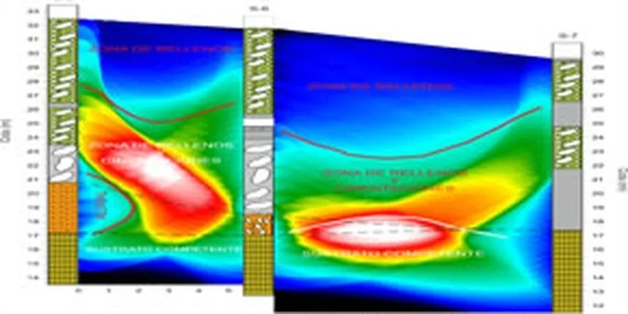
On Bath's limestone dip slope, a seismic velocity tomogram often reveals dissolution features and abandoned mine workings as low-velocity anomalies before any intrusive investigation would detect them.
Service characteristics in Bath
Critical ground factors in Bath
A 24-channel seismograph array laid across a Bath construction site looks deceptively simple—orange cables, metal geophones planted in a straight line, a trigger switch wired to a sledgehammer plate. But the real complexity lies in the interpretation. A velocity tomogram is not a photograph; it is a mathematical inversion of first-arrival times, and in Bath's limestone, where lateral velocity contrasts can be sharp due to mineralised fracture zones or clay-filled dissolution pipes, the inversion can produce artefacts that look like real features. The most significant risk we encounter is the misidentification of a velocity gradient as a discrete lithological boundary, which can lead to an incorrect rippability assessment or an overly optimistic depth-to-rock estimate. This is particularly acute where the Bath Oolite transitions laterally into the Chalfield Oolite, as the two units can show overlapping velocity ranges. We mitigate this by running reciprocal shots, analysing the delay-time curve, and—crucially—calibrating every seismic line against at least one borehole or trial pit so the velocity model is tied to physical lithology. Without that ground-truth, a tomogram is just a colourful image.
Our services
Our seismic tomography work in Bath covers three distinct service levels, from rapid reconnaissance to detailed characterisation for structural design. Each survey is designed around the specific geological question—whether that is mapping bedrock rippability for a basement excavation, locating abandoned mine workings beneath a proposed extension, or measuring the thickness of landslide debris on a valley-side plot.
Seismic Refraction for Bedrock Profiling
A 24- or 48-channel refraction survey with 2–5 metre geophone spacing, processed using tomographic inversion to produce a continuous P-wave velocity cross-section. We deliver depth-to-bedrock contours, rippability classification per Caterpillar D9R specifications, and a layer-based velocity model suitable for input to foundation design. This is our standard survey for basement excavations and cut-and-fill assessments on Bath's hillside sites.
High-Resolution Seismic Reflection
Where the target is deeper than 30 metres or where a refraction survey would miss a low-velocity layer (a hidden cavity, for example), we deploy a reflection array with tighter geophone spacing and a higher-energy source. Common applications in Bath include imaging the base of the Great Oolite, mapping the depth to the Lias Clay beneath valley-floor alluvium, and investigating suspected mine workings beneath the Combe Down area.
Cross-Hole and Down-Hole Seismic Tomography
When a project already has boreholes drilled, we run cross-hole or down-hole seismic surveys to measure P-wave and S-wave velocity directly between or within boreholes. This provides the highest-resolution velocity data available and is used for dynamic soil modulus calculations, seismic site classification per BS EN 1998-1, and calibration of surface seismic lines.
Quick answers
What depth can a seismic refraction survey reach on Bath's limestone?
With a 48-channel array and a geophone spread of 60 metres, a sledgehammer source typically images to 15–25 metres in the Bath Oolite. Using an accelerated weight drop extends the investigation depth to 40–60 metres, depending on the velocity structure. The key limitation is the velocity inversion problem: if a softer layer underlies a harder one (e.g., clay-filled dissolution pipes beneath competent freestone), refraction will not detect it. In those cases we recommend combining refraction with a reflection survey or with targeted boreholes.
How much does a seismic tomography survey cost in Bath?
For a typical 24-channel refraction survey with one to two lines totalling 100–200 lineal metres, the cost ranges from approximately £1,910 to £4,420 depending on line length, access conditions, and the number of shot points required. Reflection surveys and cross-hole tomography are priced individually based on the depth of investigation and the number of boreholes or geophone spreads involved.
Can seismic surveys be carried out near listed buildings in Bath's conservation areas?
Yes, and this is one of the main reasons we deploy seismic methods in Bath. A sledgehammer source generates minimal ground vibration—far below the thresholds that would concern a structural engineer—and the geophones are simply planted at surface level with no drilling required. We have run refraction lines within two metres of Grade I listed structures without issue, though we always coordinate with the planning authority and produce a method statement addressing vibration, noise, and access.
What is the difference between seismic refraction and MASW for site classification?
Seismic refraction measures P-wave velocity, which is sensitive to both the rock matrix and the water table, while MASW measures S-wave velocity, which is unaffected by groundwater and relates directly to the small-strain shear modulus. For seismic site classification to BS EN 1998-1, we need the average S-wave velocity in the upper 30 metres (Vs30), which is typically obtained by MASW or down-hole seismic. In Bath we often run MASW alongside refraction so that both P-wave and S-wave velocity models are available—the combination gives us Poisson's ratio and helps distinguish saturated from dry zones.